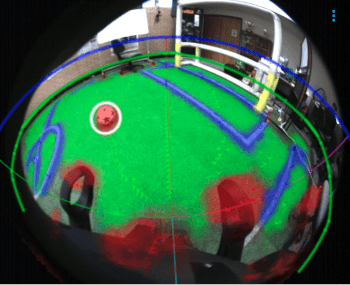
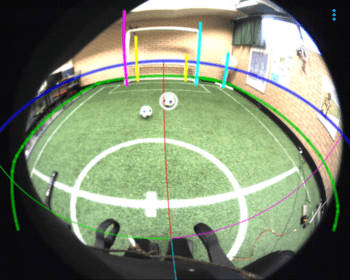
The vision system aims to convert images from a camera in the robot into useful information, such as the position of balls, goal posts, field lines and obstacles. This information is used to determine behaviour and localisation. The vision subsystem includes object detection and post-processing.
Visual Mesh
Algorithm
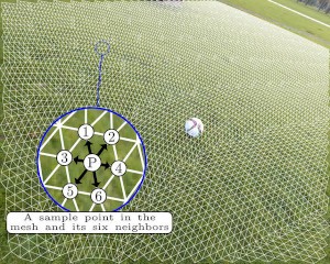
The Visual Mesh underpins the vision system and is used for sparse detection of balls, points on the field, field lines, goal posts and other robots. It is an input transformation that uses knowledge of a camera's orientation and position relative to an observation plane to increase the performance and accuracy of a convolutional neural network. It utilises the geometry of objects to create a mesh structure that gives high accuracy of detection regardless of the distance to the object.
The height and orientation of the camera is tracked using the kinematics and inertial measurement unit of the robot. The lens type and the expected radius of any soccer ball are given as a configuration value. These values are used to create a set of unit vectors with the origin at the camera position. These unit vectors represent rays of light travelling towards the camera. Each vector is mapped to a point on the image using an appropriate lens projection equation. Two equations are used to efficiently sample the space around the camera to obtain the array of vectors and associated sample points.

Each sample point is connected to its six closest neighbours. These connections become the edges of the mesh. A fully convolutional neural network is used on the mesh where each sample point and its neighbours become the input to a convolution. All layers in the network use seven point convolutions, representing a point and its six neighbours. The number of sample points determines the level of detail available to the network. The output of the network is a label to each point specifying what class it belongs to. This could be a ball, goal-post, field, field line, robot, or none.
The mesh constructed is one possible mesh. Various meshes can be created with different values for the height, orientation, lens type and radius of a soccer ball. The algorithm creates many different meshes for different height and radius pairs on startup. For each image, we find the appropriate mesh based on the height and radius values for that image. The vectors used for the mesh are determined based on the orientation, and are selected using binary search.

Implementation
The Visual Mesh implementation can be found on GitHub. It has implementations for using circle, spherical or cylinder geometry for the mesh. The Visual Mesh implementation uses TensorFlow for training. The Visual Mesh can be used with the CPU engine with C++ code or it can be used with the OpenCL engine on CPUs and many GPUs.
In the NUbots codebase, the Visual Mesh is used in the Visual Mesh module. Network biases and weights are found in the configuration file in the module, along with other Visual Mesh parameters such as geometry type. The module receives an Image message from the Camera module, detailed above, and inputs it into the Visual Mesh. The resulting mesh and classifications are output as a VisualMesh message. This message can then be used in post-processing.
Post-Processing
From the Visual Mesh a series of specialised detectors are employed to detect field edges, balls, and goal posts. The green horizon detector uses information from the Visual Mesh message as detailed above. The goal and ball detectors use the information given by the green horizon detector in the GreenHorizon message.
All calculations in the detectors are done in 3D world coordinates. To find out more about the mathematics used at NUbots, check out the mathematics page.

Green Horizon Detector
When the green horizon detector receives a VisualMesh message, it uses the information in this message to create one large cluster of points that is determined to be the field.
The points are first filtered to give only potential field points, based on a confidence threshold. The first field point is added to a cluster with all its field point neighbours. Neighbouring field points are added to the cluster until all field points who are neighbours of the points in the cluster are added to the cluster.
Clustering is repeated until all field points are part of a cluster. Clusters that are smaller than a given threshold are discarded. Clusters are merged unless they overlap. If the clusters overlap, we keep the larger cluster and discard the smaller cluster.
After clustering has finished, one cluster will remain which should represent the field. An upper convex hull algorithm is applied to the final cluster to determine the edge of the field. The detector will emit a GreenHorizon message that specifies the location of the edge of the field.
Ball Detector
The ball detector receives a GreenHorizon message and a FieldDescription message. The FieldDescription message is output by the SoccerConfig module which creates the FieldDescription message from configuration values specifying the layout of the soccer field as well as the radius of the ball being used.
The ball detector forms clusters out of all the points that the Visual Mesh has determined are likely to be ball points. The clusters are formed from Visual Mesh points that have a ball confidence above a certain threshold and have at least neighbour which has a ball confidence below this threshold. This allows the formation of clusters of ball edge points. Clusters are discarded if
The cluster is not below the green horizon.
The cluster is smaller than a given threshold.
Remaining clusters are fitted with a circular cone. The cone axis is determined from the line segment between the centre of the camera and the centre of the ball, determined by averaging all of the ball edge points. The radius of the cone is determined by the maximum distance between the ball edge points and the centre of the ball. Clusters are discarded if they fail to meet any of the following criteria
The cluster fits the shape of a circle well enough to be a ball. We use a degree of circle fit to determine this. This involves calculating the standard deviation of the angle between all the rays in the cluster. The standard deviation must not exceed a given threshold.
- is the cone axis of the cluster
- is the ray vector of the th point in the cluster
- is the maximum radius allowed
The distance to the cluster is larger than a given minimum distance.
The difference between the angular and projection-based sizes of the cluster is within a given threshold.
- is the angular-based size
- is the projection-based size
- is the actual ball radius we are expecting
- is the calculated cluster radius
- axis is the cone axis as specified above
- rWCc is the vector from camera to world in camera space. For more information on this convention, see the Mathematics page.
The cluster must have a distance less than the length of the field, as given by the FieldDescription message.
Any remaining clusters are assumed to be balls and so are emitted together as a Balls message.
Goal Detector
The goal detector follows a similar structure to the ball detector. It receives a GreenHorizon and a FieldDescription message.
All goal post edge points (points that are goal points that have at least one neighbour that is not a goal point) are found and partitioned into clusters. A point is a goal point if it has a goal confidence higher than a given threshold. Clusters are discarded if
The cluster does not intersect the green horizon (goals are assumed to extend higher than the field, and therefore intersect the green horizon)
The cluster is smaller than a given threshold
From the remaining clusters, clusters are merged if they lie on the same vertical vector. This is to prevent detection of the same post twice and to prevent detection of back posts. The bottom centre point of each cluster is then found by averaging the edge points. This is the point where we measure the distance from. If this distance is too large, as defined in the configuration file, the goal post is discarded.
If there is more than one cluster, i.e. more than one goal post, an attempt is made to pair up the goal posts. This is done by calculating the distances between the posts and pairing up goal posts that are close together. Leftness and rightness is assigned to each post in a pair based on their positions.
The goal detector then emits any goals as a Goals message. Note that while this message contains information on if a goal post is a left or right post, it does not send information on what goal post it is paired with.
References
E. Shelhamer, J. Long, and T. Darrell. Fully convolutional networks for semantic segmentation. IEEE Transactions on Pattern Analysis and Machine Intelligence, 39(4):640–651, April 2017.
Trent Houliston and Stephan K. Chalup. Visual mesh: Real-time object detection using constant sample density. CoRR, abs/1807.08405, 2018.
Erik Krause et al.. Fisheye Projection. Panotools, 2019. https://wiki.panotools.org/Fisheye_Projection

